How to Check Walk-In Freezer Defrost Timer
Excessive frost buildup in your walk-in freezer isn’t just inconvenient—it can cripple your refrigeration system’s efficiency and put your entire inventory at risk. The defrost timer silently manages this critical function, automatically triggering defrost cycles to melt ice from evaporator coils. When this component fails, you’ll notice temperature fluctuations, increased energy bills, and potentially thousands in lost product. Learning how to check defrost timer on walk-in freezer systems empowers you to diagnose problems before they escalate, saving costly emergency service calls and preventing inventory disasters. This guide delivers precise, step-by-step testing procedures used by professional technicians to verify timer functionality.
Most commercial walk-in freezers operate on 4-12 hour defrost cycles, with each cycle lasting 20-45 minutes. A malfunctioning timer can cause either insufficient defrosting (leading to ice blockage) or excessive defrosting (causing dangerous temperature spikes). Whether you’re dealing with a mechanical synchronous motor timer or a modern electronic controller, these diagnostic methods will pinpoint exactly where the problem lies so you can take immediate corrective action.
Locate Your Defrost Timer in Under 2 Minutes
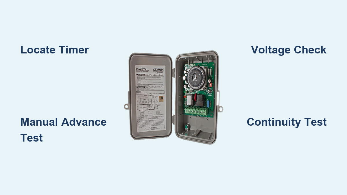
Finding your walk-in freezer’s defrost timer requires knowing where manufacturers typically install these critical components. Start your search on the exterior control panel where most units mount the timer near the compressor compartment. Look for a small rectangular device with either a rotating dial (mechanical timers) or digital display (electronic models). Mechanical timers feature a 24-hour dial marked in 15-minute increments with adjustable pins that trigger defrost cycles at set intervals. Electronic versions display current status, time until next defrost, and diagnostic information.
If you don’t spot it externally, check inside the freezer near the evaporator coil housing or along the sidewall adjacent to refrigeration lines. Some manufacturers install timers in remote control boxes separate from the main unit. Once located, note the model number and manufacturer—this information becomes crucial if replacement is necessary. Before disconnecting any wires, take a clear photo of the current wiring configuration to prevent connection errors during reassembly or testing.
How to Identify Timer Type at a Glance
Distinguishing between mechanical and electronic timers takes seconds when you know what to look for. Mechanical timers have a visible rotating dial showing the current time of day, with small pins you can manually adjust to set defrost initiation points. You’ll hear a faint humming sound from the internal synchronous motor when power is applied, and you should see slow but perceptible movement of the timing dial within minutes of observation. Electronic timers feature LED or LCD displays showing operational status, countdown timers, and sometimes error codes. These units often have push buttons for manual advancement and parameter adjustment rather than physical dials.
Critical Location Variations by Manufacturer
Different manufacturers install defrost timers in distinctive locations that can speed up your search. Carrier units typically mount mechanical timers inside the control panel box on the exterior right side of the freezer. York systems often place electronic controllers near the evaporator coil housing inside the freezer compartment. Hussmann walk-in freezers frequently install timers in a dedicated electrical compartment beneath the refrigeration unit. If you’re working with an older unit, check behind access panels on the condensing unit—some vintage models conceal timers in these hard-to-reach locations.
Visual Inspection That Reveals 80% of Timer Problems

Before grabbing your multimeter, conduct a visual inspection that often identifies issues without electrical testing. Start by examining the timer housing for physical damage: cracked covers, darkened areas indicating overheating, or moisture intrusion that causes internal corrosion. For mechanical timers, verify the motor is running—you should see the small gear rotating continuously when power is applied. A complete 24-hour dial rotation should take approximately 24 hours, so perceptible movement should occur within minutes of observation.
Electrical Connection Warning Signs
Inspect all terminal connections for telltale signs of problems that cause intermittent operation. Look for corroded terminals showing green or white powder deposits, discolored copper indicating overheating, or melted wire insulation exposing bare conductors. Gently tug on each wire to verify secure attachment—loose connections cause erratic timer performance. Check wire insulation for cracking from age or rodent damage, especially near sharp metal edges. If the timer is mounted in a vibration-prone area, ensure mounting screws remain tight and that the timer hasn’t shifted position, which can strain wire connections.
Decoding Timer Indicator Lights
Most defrost timers incorporate status lights that provide immediate diagnostic information without tools. A continuously illuminated power indicator confirms electrical supply to the timer. The defrost indicator should illuminate only during active defrost cycles (20-45 minutes)—if this light stays on for hours, you likely have a defrost termination thermostat failure or excessive ice preventing proper heat transfer. Some timers feature “timed” and “terminated” indicators showing whether defrost ended due to timer expiration or thermostat activation. A compressor indicator should illuminate when the refrigeration system is actively cooling, while a fan indicator displays evaporator fan operation status.
Manual Timer Advance Test That Confirms Functionality
Performing a manual advance test verifies timer operation without waiting for scheduled defrost cycles—a critical diagnostic step when troubleshooting suspected timer failures. Locate the advance mechanism: mechanical timers have a small protruding tab or screw head on the timer face, while electronic models require specific button sequences. Using a flathead screwdriver, slowly rotate the mechanical timer clockwise while listening for distinct audible clicks as the mechanism passes through cycle points.
Step-by-Step Manual Advancement Procedure
- With power ON, observe the defrost indicator light (if equipped)
- Locate the manual advance shaft (typically a small protrusion on timer face)
- Using a screwdriver, gently rotate the shaft clockwise in 15-minute increments
- Listen for the audible “click” as the timer passes defrost initiation point
- Verify the defrost indicator illuminates and heater circuit activates
- Continue advancing past the defrost termination point (another click)
- Confirm the defrost indicator turns off and compressor resumes operation
If the timer fails to switch states at expected points or produces no audible clicks, the internal mechanism is faulty and requires replacement. Electronic timers may require holding specific buttons for 3-5 seconds to initiate manual advancement—consult your model’s documentation for precise procedures.
Voltage Testing That Pinpoints Electrical Failures

Voltage verification confirms whether electrical power reaches the timer and if the timer properly supplies power to downstream components. After implementing safety protocols (disconnecting power, verifying with multimeter, wearing PPE), restore power and set your multimeter to AC voltage. For 120V timers, expect readings between 108-126V; for 240V timers, look for 210-252V readings across line terminals (typically marked L1/L2).
Critical Voltage Measurement Points
Measure voltage at three essential locations to diagnose timer functionality:
– Line terminals: Confirms power supply integrity to the timer
– Defrost heater terminals during defrost cycle: Should read line voltage when timer is functioning properly
– Compressor terminals outside defrost cycle: Should read line voltage when cooling is active
To test heater circuit operation, either wait for a scheduled defrost cycle or manually advance the timer into defrost mode. With the timer in defrost position, measure voltage across the heater terminals (typically marked H1/H2). A reading equal to line voltage confirms the timer is properly supplying power to the heating elements. No voltage during active defrost indicates timer contact failure, blown fuse, or open circuit in the heater wiring.
Continuity Testing That Finds Hidden Defects

Continuity testing identifies internal timer problems invisible to visual inspection. With power completely disconnected, set your multimeter to continuity or resistance mode. For mechanical timers, test the motor winding by measuring resistance between motor terminals—you should read 100-500 ohms depending on voltage rating. Infinite resistance indicates an open winding requiring timer replacement.
Contact Testing Protocol
Test the switching contacts by measuring continuity between appropriate terminals during different cycle phases. Rotate the timer dial to simulate various positions. At defrost initiation point, continuity should exist between power input and heater output terminals. At all other times, this continuity should be absent, with continuity instead present between power input and compressor terminals. You should hear audible clicks as the mechanism passes through defrost points.
Critical continuity checks:
– Motor winding resistance (100-500 ohms)
– Defrost circuit continuity during defrost position
– Compressor circuit continuity outside defrost position
– Fan circuit continuity (if applicable)
Any absence of continuity where expected, or continuity where it should be absent, confirms timer failure requiring replacement. Always compare your readings against the wiring diagram specific to your walk-in freezer model.
Verify Defrost Timing Accuracy That Prevents Future Failures
Accurate timing ensures defrost cycles occur at proper intervals and run for appropriate durations. For mechanical timers, time the complete rotation of the 24-hour dial—it should take exactly 24 hours (±15 minutes) for one full rotation. If the motor runs significantly faster or slower, your timing will be inaccurate, leading to either excessive ice buildup or damaging temperature fluctuations.
Timing Verification Methods
Use one of these two methods to verify defrost timing accuracy:
1. Observation method: Note the exact time when a defrost cycle begins by monitoring the defrost indicator. Return 24 hours later to verify the next defrost cycle starts within 15 minutes of the same time.
2. Data logging method: Use a multimeter with data logging capability to record precise timing of defrost cycle initiation and termination over 24-48 hours, then compare against timer settings.
For electronic timers, many models display the time until next defrost, allowing you to verify accuracy without round-the-clock observation. If timing deviates more than 15 minutes from expected intervals, the timer mechanism is failing and requires replacement before it causes operational problems.
Test Associated Components That Mimic Timer Failures
A properly functioning defrost system depends on multiple components working together—timer failure isn’t always the culprit. Test the defrost termination thermostat by placing it in an ice bath (should show continuity when cold) then allowing it to warm (should open circuit above 35-45°F). A thermostat that fails to open causes excessive defrost duration, while one that opens prematurely results in incomplete defrosting.
Essential associated component tests:
– Defrost heaters: Measure resistance (10-50 ohms for 120V, 20-100 ohms for 240V)
– Evaporator coil temperature during defrost (should exceed 35°F)
– Interior temperature recovery time (should return to normal within 30-60 minutes)
Ice accumulation patterns provide valuable diagnostic clues—uniform buildup across the entire coil typically indicates timer issues, while localized ice suggests airflow or refrigerant problems. Document these observations alongside your timer tests to pinpoint the exact cause of defrost system failures.
When to Replace Your Defrost Timer Immediately
Certain symptoms definitively indicate timer replacement rather than repair. Mechanical timers with noisy motors, visible gear damage, or contacts that fail to switch require complete replacement. Electronic timers with blank displays, unresponsive controls, or persistent error codes likewise need replacement. Timers showing signs of moisture damage, burning, or melting must be replaced immediately to prevent fire hazards.
When replacing your timer, obtain the exact manufacturer-specified replacement—substitutes may have incompatible terminal configurations or timing ranges. Transfer all settings from the old timer to the new unit: for mechanical models, adjust defrost interval pins to match original settings; for electronic timers, program correct parameters. After installation, observe at least one complete defrost cycle to confirm proper operation before considering the job complete. Document the replacement in your maintenance records with the new timer’s serial number and installation date for future reference.